
Display Screens
- Video Output Monitor
- Displays the output video stream
- Multi-Viewer Monitor
- Upper Display
- Next - Row B camera selection
- PGM - Row A camera selection, output video stream
- Middle Display
- Four sequential video streams displayed
- Screens are highlighted based on selection; Green Row B/Next, Red Row A/PGM
- Lower Information
- PGM L/R: Sound input to videomixer
- Recording details displayed
- Note: time counter is since the device was turned on, not the length of recording
- Upper Display
- Video Mixer
Control Panel
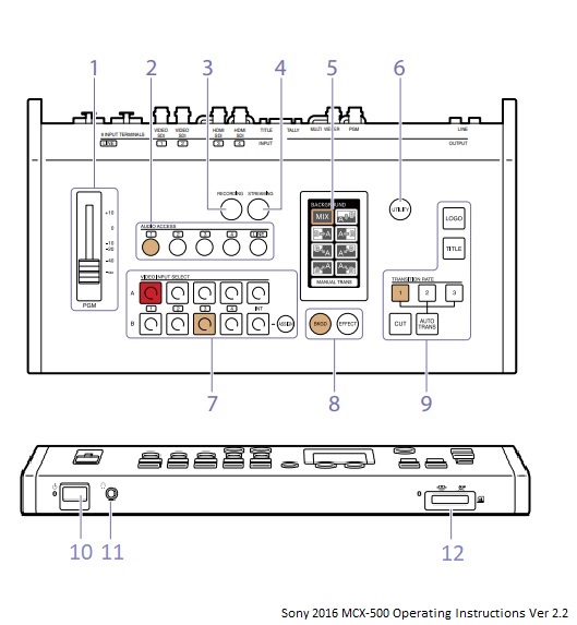
- PGM Master Fader: Audio output level adjustment
- Can be monitored via headphones connected to 11
- Setting should be around -10
- Audio Access Buttons: Displays menus (5) for adjusting the audio
- Can switch between audio inputs using the buttons.
- When the input is being used for output, the button will turn brown.
- Camera inputs are 1-4 and ceiling microphones is LINE input
- Note: LINE input & camera simultaneously creates a noisy signal
- LINE input is from the ceiling microphones
- Microphone preamp (bottom of audio rack) needs to be turned on for use
- More details on the preamp can be found here
- Recording Button: Displays menu (5) for performing recording operations
- Button will turn red when recording is in progress
- Streaming button: Displays menu (5) for performing streaming operations
- Button will turn blue when streaming is in progress
- Menu panel: Touch panel used for controlling video mixer
- Utility Button: Adjust utilities in menu panel (5)
- Headphone volume, menu brightness, etc
- Video Selection Block: Buttons for controlling video input
- Row B buttons - select which input is displayed for "next". Button will be brown or green. If using PinP, this row is used to select the overlay video.
- Row A buttons - Selects which input to be used for PGM output. Button will be red when that camera is set to output.
- Note: the assign button allows for customization of input channels. This should not be used.
- Delegation Block: Selects video switching mode
- BKGD (brown) - used for transitioning videos
- Effect (green) - used for compositing videos
- Transition Block: A collection of buttons used to perform and control transitions
- Power switch
- Indicator will be green when on and red when off
- Headphone Jack
- Headphones attached to the videomixer should not be removed
- Memory Card Slot
- For recording PGM outputs. Memory Stick Duo or SD card can be used and should be inserted facing up.
Additional information can be found in the product manual