CAS Trumpet Mod Prototype
Introduction
I have
built a prototype of the CAS Trumpet Mod. This is a
meta-trumpet; an augmented instrument system consisting of attachable sensors,
sound engine and mapping strategies enabling simultaneous interaction with both
the trumpet and different software based musical tools.
This is project
both the semester assignment for the class MUS2830
Interactive Music at the University of Oslo, and the first part of the Chasm Interactive Music Technology Project. This
documentation will also be published on my blog: http://chasmmusic.wordpress.com/.
Although
the sketches and thought processes leading up to the development of the CAS Trumpet Mod has been largely characterized by
on-and-off simultaneous brainstorming around different challenges and ideas, I
have structured the information to provide a good overview of the different
topic areas. The presentation is based around the approach to designing Digital
Musical Instruments (DMI�s) suggested by Miranda and Wanderley
in New Digital Musical Instruments:
Control and Interaction Beyond the Key (Miranda/Wanderley
2006:4).
Anyone who
wish to do so may emulate the work presented in this paper as long as the
development is for non-commercial use, does not violate the rights of other
research material presented in this paper, and all information presented in
this paper is referred according to "god skikk".
As the
essential parts of the system were functional about a month ago, I initially planned
to finish not only the prototype, but also the CAS
Trumpet Mod v. 0.1 by this time. However,
I found that additional testing and analysis was needed to provide a more solid
foundation for development beyond the prototype. This report therefore focuses both
on developing the system and on various challenges related to its musical
interactivity.
For the CAS Trumpet Mod Prototype I have used sensors from the PhigdetInterfaceKit.
The digital platform used is MAX by
Cycling 74.
Background
As
mentioned, the development of the CAS Trumpet Mod is
a part of the Chasm Interactive
Technology Project. Through this project I am seeking new ways of creating
music. "I aim to create flexible
and expressive electro-acoustic setups enabling the performer to instantly
create any soundscape that comes to mind"(Svalesen). The purpose of the project
is to develop customized tools for me to use both when I play live improvised
electro-acoustic soundscapes and when I wish to enhance/change the role of the
trumpet in more conventional bands.
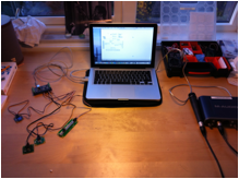
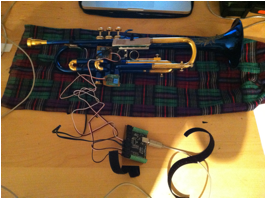
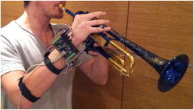
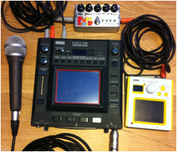 This is the set up I currently use for
improvising soundscapes.
This is the set up I currently use for
improvising soundscapes.
It
consists of a Kaosspad, a Zvex Fuzzfactory, a Kaossilator, a trumpet and a
microphone. I usually play into the microphone, which sends the sound directly
into the Kaosspad. Here, the sound is processed with effects, sampled,
re-sampled with new effects etc. The Kaossilator is essentially a small touch
synthesizer with 100 different pre-programmed sounds. The signal from this is
sent through the Zvex Fuzzfactory, which is a stompbox
fuzz, and into the Kaosspad. The Kaosspad cannot get input from the Kaossilator
(line input) and Microphone (Mic input)
simultaneously and thus operating the Kaosspad while playing Trumpet has quite
a few restrictions. For example, to quickly change pitch on the trumpet while maintaining
a stable tone requires both hands, making it difficult to play faster phrases
while interacting with the electronics. When using my current set up, I usually
alternate between being either mostly an electronics player or mostly a trumpet
player.
To solve
this problem, I have been working on a concept on how to integrate the
electronics with my trumpet playing. The goal is to create a device that
enables the electronics and the trumpet to be experienced by the performer as
one combined instrument, rather than two separate.
Another
limit to my current set up is the time it takes to heavily process sounds. I
first have to sample the sound, and then resample for each effect I wish to add.
Although this works well when one builds slowly evolving soundscapes, it is far
from ideal when more dynamic and rapidly evolving sounds are required. As a part of my project I am therefore
also stepping into the world of computer based live electronics, planning to
use Max and Ableton Live as platforms for my new
controller. Through these
platforms, I wish to be able to create a nearly limitless setup, so that any
soundscape that may come to mind can be unfolded in a matter of seconds.
Task
With this
in mind, I decided upon the following goal for my assignment:
"To
develop a functioning prototype which enables simultaneous interaction with
both trumpet and electronics, while exploring the different challenges related
to musical interaction with this controller"
Planning
and development:
I wanted
to be able to utilize the enhanced possibilities the controller could provide and
combine this with the previously well-learned trumpet technique. I therefore chose to derive the signal
data for the digital part of the controller from additional physical gestures available
in normal interaction with the trumpet. The result would be an augmented instrument,
combining an acoustic instrument and a digital gestural controller
(Miranda/Wanderley.2006: 21).

Figure 1:
Model representing the augmented trumpet. Different gestures from the performer
control the acoustic and electronic parts of the instrument. These two routes
are combined in the Sound/effects engine to merge into one output audio signal.
![]()
Figure 2:
Representation of the Controller.
![]()
Figure 3:
Representation of Sound Engine.
These
representations are based on the model for DMI�s
presented by Alexander Refsum Jensenius
in the lecture "Musikalsk
Elektronikk" (Jensenius.2013)
a. "Decide on gestures"
(Miranda/Wanderley.2006:
4)
The first
step suggested by Miranda/Wanderley is to decide what
gestures will be used to control the system. The definition on gestures is here
set to: "any human action used to generate sound" (Miranda/Wanderley
2006:5). I decided to use the possible movement from fingers that are usually unoccupied
when playing the trumpet, and started with these four: left thumb, left index
finger, left pinky and right thumb. The instrumental gestures these fingers
would execute would be what Calude Cadoz referred to as ergotic gestures, as there would be "energy transfer between the hand and the
object". An exception would be the instrumental gesture performed by the right
thumb on the touch sensor. This would be an Epistemic
Gesture as it is based on " our capacity of touch" rather than the
previously mentioned "energy
transfer" (Miranda/Wanderley.2006: 9). All of these would further be based on direct gesture aquistion
as the sensors directly monitor the actions, or instrumental gestures, of
the performer (Miranda/Wanderley.2006: 12).
b. "Define gesture capture
strategies"
(Miranda/Wanderley.2006:
4)
In this
step one decides how to best translate the gestures from step a. into
electrical signals. What kind of sensors will be used and which gesture
variable will be captured?
In this
step I will also discuss the development process of the prototype hardware. In
addition to decisions regarding sensor type and gesture capture, this process
also included challenges related to sensor placement and stability.
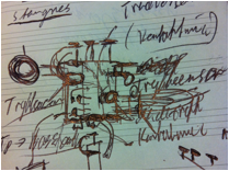
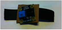
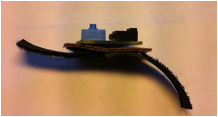
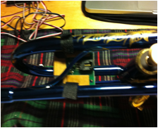
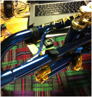
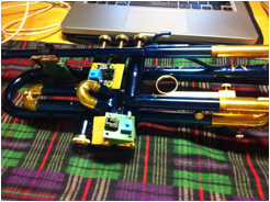
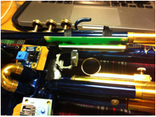
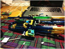
 The first picture is an early concept sketch exploring possibilities for
sensor placement and interaction possibilities. The second is another early sketch
illustrating the potential chaos of signal cables. Although this does not pose
a significant challenge with the prototype, one might be faced with this
challenge given the addition of more sensors in later versions. A solution
could be wireless transfer of signal data to the sound engine through an IPhone
application. This could, however, result in latency problems. Minor differences in timing may not
critical in more open soundscapes, but for the CAS
Trumpet Mod to be functional in extended horn sections, the effects triggers
need to be as accurate as absolutely possible. I therefore prefer to keep the sensors
and the sound engines connected by physical wires as long as this does not
significantly affect performance mobility.
The first picture is an early concept sketch exploring possibilities for
sensor placement and interaction possibilities. The second is another early sketch
illustrating the potential chaos of signal cables. Although this does not pose
a significant challenge with the prototype, one might be faced with this
challenge given the addition of more sensors in later versions. A solution
could be wireless transfer of signal data to the sound engine through an IPhone
application. This could, however, result in latency problems. Minor differences in timing may not
critical in more open soundscapes, but for the CAS
Trumpet Mod to be functional in extended horn sections, the effects triggers
need to be as accurate as absolutely possible. I therefore prefer to keep the sensors
and the sound engines connected by physical wires as long as this does not
significantly affect performance mobility.
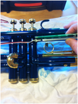
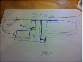 This is a crude sketch showing practical placement of the different
sensors. Although there has been made some changes, the prototype is based
mostly on this layout. Button 1 and Button 2 in the sketch were initially
on/off button switches. In the prototype force sensors replaced these, though
still set in the same positions. The switch triggered by the right thumb (top
left in sketch) was in the prototype development replaced by an on/of touch sensor
as I wished to explore the capabilities of this sensor type. Only the slider
mounted near the lead pipe was implemented without alterations.
This is a crude sketch showing practical placement of the different
sensors. Although there has been made some changes, the prototype is based
mostly on this layout. Button 1 and Button 2 in the sketch were initially
on/off button switches. In the prototype force sensors replaced these, though
still set in the same positions. The switch triggered by the right thumb (top
left in sketch) was in the prototype development replaced by an on/of touch sensor
as I wished to explore the capabilities of this sensor type. Only the slider
mounted near the lead pipe was implemented without alterations.
I
borrowed a PhidgetsInterfaceKit
from the Institute of Musicology and used sensors from this kit as the hardware
basis of the CAS Trumpet Mod Prototype. All sensors to be used for the prototype
were contact sensors, as they needed to be in physical contact with the source
of energy (read fingers) for the
stimuli to be converted into electrical signals. (Miranda/Wanderley.2006: 105).
Two force sensors were to be used to register the gestures from the left thumb
and the left pinky respectively. A slider was to be used to register the position
of the left index finger, while an On/off Touch sensor captured the gesture of the
right thumb.
 The next task was to check whether the positions planned in the sketches
could work, and if so, how to attach the sensors to the trumpet. The sensors
needed to be stable in position when attached to allow the best possible
functionality of the augmented instrument. But they also needed to be easy to remove
and not to damage the instrument in any way, as I wanted to be able to continue
to use the trumpet traditionally as well.
The next task was to check whether the positions planned in the sketches
could work, and if so, how to attach the sensors to the trumpet. The sensors
needed to be stable in position when attached to allow the best possible
functionality of the augmented instrument. But they also needed to be easy to remove
and not to damage the instrument in any way, as I wanted to be able to continue
to use the trumpet traditionally as well.
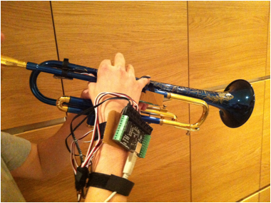
Force Sensor no.1
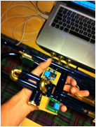
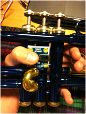 It was important that the
force sensors could be manipulated without inhibiting the functionality of the
other fingers. The finger responsible for manipulating the sensor also needed
to be able to execute adequate pressure on the sensor, so that the mapped
effects/sounds could be manipulated expressively. I am here testing the placement of
the first force sensor, and how executing force on the sensor affects the movability
of the other fingers. I found that the thumb could be able to execute
relatively large amounts of pressure on the sensor without affecting the other
fingers, as long as the palm rested on the backside of the valve casings. Note
also that the left pinky is unoccupied.
It was important that the
force sensors could be manipulated without inhibiting the functionality of the
other fingers. The finger responsible for manipulating the sensor also needed
to be able to execute adequate pressure on the sensor, so that the mapped
effects/sounds could be manipulated expressively. I am here testing the placement of
the first force sensor, and how executing force on the sensor affects the movability
of the other fingers. I found that the thumb could be able to execute
relatively large amounts of pressure on the sensor without affecting the other
fingers, as long as the palm rested on the backside of the valve casings. Note
also that the left pinky is unoccupied.
To
achieve more stability, I decided to mount the sensor on a small plate. Cardboard
was used for all plates as it is cheap, easy to work with, does not scratch the
trumpet, and hard enough to achieve the desired stability. For the more permanent parts for the CAS Trumpet Mod v.1 I am considering either smooth edged
plastic plates or 3D printed parts. The latter method has been successfully
used by by Onyx Ashanti to create his
"Beatjazz" controllers (Ashanti).
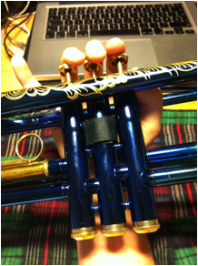
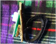
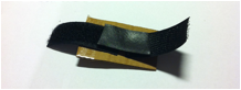 The attachment mechanism was built fastening Velcro and a piece of
rubber tape to the cardboard plate using Multi Tac Putty and staples. The Velcros
function was to enable the sensor to be attached around the middle
The attachment mechanism was built fastening Velcro and a piece of
rubber tape to the cardboard plate using Multi Tac Putty and staples. The Velcros
function was to enable the sensor to be attached around the middle
 valve tube as shown below.
The piece of rubber tape provided the necessary friction for the sensor to stay
in place while also functioning as a protecting layer between the staples and
the valve casing.
valve tube as shown below.
The piece of rubber tape provided the necessary friction for the sensor to stay
in place while also functioning as a protecting layer between the staples and
the valve casing.
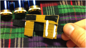
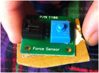
 The sensor mounted on the attachment
mechanism. Although consisting of several layers, the combined part turned out
quite slim.
The sensor mounted on the attachment
mechanism. Although consisting of several layers, the combined part turned out
quite slim.
The Velcro attachment on the backside of the secong valve
tube. Note that the attachment mechanism does not pose a hindrance for the left
hand position.
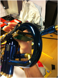
Touch
Sensor
The
attachment mechanism for the on/off touch sensor proved to be more of a
challenge. The sensor was to be mounted underneath the lead pipe and the final
pipe before the bell and I therefore had to build a somewhat more complex
cardboard plate as shown above. This resulted in the combined part shown
attached in the pictures below. Note the easy access from below to the touch
sensor plate.
The
output slot on the upper side of the sensor was also part of the reason for the
increased complexity its attachment mechanism. The output slot had to be fitted
between the pipes while still avoiding the supporting stem.
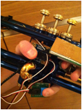
Force sensor no.2
The Force
sensor no.2 was to be controlled by the left pinky, and the attachment
mechanism for this was made nearly identical to that of Force sensor no.1. Note
the small difference in inclination of the sensor to provide increased accessibility.
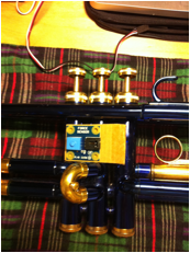
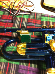
Both force sensors and the touch
sensor shown mounted below.
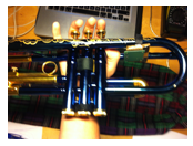
The
sensors still pose no hindrance to the positioning of the left hand.
Slider
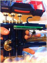
Checking the position of the slider to be controlled be the
left index finger. The sensor was to capture the finger position and thus it
was important to secure finger mobility.
The
slider was attached using the same Velcro/rubber tape system as the previous
sensors. I also attached a metal ring to the slider knob inspired by that of
the third valve tube of the trumpet. This would make it easier for the sensor
to register finger movements.

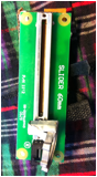
The
cardboard plate added on top provided increased stability as well as a more
elegant look from the outside angle.
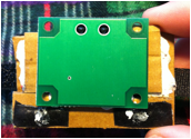
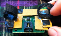
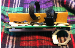
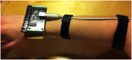
PhidgetInterfaceKit 8/8/8
This was
to be the ADC of the system and it needed to be in relative proximity to the sensors
to avoid unnecessary cable chaos. I therefore decided to mount it on a
cardboard plate, which could then be attached to the right hand of the
performer using Velcro. I added two more Velcro bands further down the USB
cable so this one could be attached to the right forearm of the performer.
Finished
Prototype Hardware
c. "Define sound synthesis algorithms that will create
the sounds to be played"
(Miranda/Wanderley.2006:
4)
In our
case this step could also be rephrased as "Define the sound effect algorithms that
will manipulate the input audio". In principle, the signals from the sensor
system described above could be mapped to any sound or effects engine. For the
Prototype, I decided to focus on input audio manipulation, or sound effects. This
way the acoustic and electronic elements leading up to the final output sound
would be both clearly separable, and at the same time perceived as one enhanced
instrument. This could make it easy to analyze how the interaction with the electronic
elements affects the total performance, and evaluate the interactive
characteristics of the augmented instrument.
Sound Engine
This step
includes programming the sound engine for the DMI. The
sound engine was developed in Max (MSP) using a
number of different patches. I used a MacBook as digital platform.
For MAX
to be able to interact with the PhidgetsInterfaceKit, it
was first necessary download the externals for the PhidgetsInterfaceKit and to introduce these into Programs → MAX6 → Cycling �74 → max
–externals.
Sound Engine 1
This
sound engine was programmed to provide a basic setup for testing and exploring
the functionality of the prototype controller. The effects used were an overdrive
and a stereo delay. These are effects that I have considerable experience with,
thus making the interaction with the controller the main focus of the setup. I
used the following approach programming:
cmd+ n : New document
cmd+ e : Edit mode
PhidgetsInterfaceKit module:
N → "PhidgetInterfacekit".
M → "Start" → Connected to inlet 1
of "PhidgetInterfaceKit"
M → "Stop" → Connected to inlet 1
of "PhidgetInterfaceKit"
M → "getVersion"
→ Connected to inlet 1 of "PhidgetInterfaceKit"
M → "getStatus"
→ Connected to inlet 1 of "PhidgetInterfaceKit"
M → "getSerial"
→ Connected to inlet 1 of "PhidgetInterfaceKit"
M → "read" → Connected to inlet 1
of "PhidgetInterfaceKit"
M → "setSamplerate
$1" → Connected to inlet 1 of "PhidgetInterfaceKit"
I → Connected to message
of "setSamplerate $1".
N → "route di ai" → Connected to output
from "PhidgetInterfaceKit"
N → "unpack 0 0 0 0 0 0 0 0" → Connected output
from "di"
I → connect to "unpack 0
0 0 0
0 0 0
0" . For each of the 4 elemtents
used.
Element
8: Slider, Element 7: Force Sensor no.1, Element 6: Force Sensor no.2, Element
5: Touch Sensor
Sound system module:
Analog to Digital Converter Collecting
Sound
N → "adc~"
M → "start" → connected to inlet
of "adc~"
M → "stop" → connected to inlet
of "adc~"
M → "startwindow"
→ connected to inlet of "adc~"
M → "open" → connected to inlet
of "adc~"
M → "wclose"
→ connected to inlet of "adc~"
T → connected to inlet
of "adc~"
N → "meter~"→ connected to "Audio
In Ch 1" of "adc~"
Overdrive Effects
N → "overdrive~" → connected to "Audio
In Ch 1" of "adc~"
N → "overdrive~" → connected to "Audio
In Ch 1" of "adc~"
N → "*~1" → connected to outlet
of "overdrive", "overdrive" and to connected to "Audio In Ch
1" of "adc~"
The
overdrive was set directly after the ADC and before the delay to enhance signal
clarity.
Delay Effects
N → "delay~ 45100" → connected to outlet
of "*~1"
N→ " *~ " → connected to outlet
of "delay~ 45100"
N → "delay~ 46100" → connected to outlet
of "*~1"
N→ " *~ " → connected to outlet
of "delay~ 46100"
N → "dac~"
→ left inlet connected to outlet of
("delay~ 45100" through "*~") and outlet of "*~6"
→ right inlet connected to outlet of ("delay~ 46100" through "*~") and outlet
of "*~6"
The "adc~" collected audio from the microphone plugged into input
1 in M-Audio Fastrack Pro external sound module. This
was achieve by changing the settings in Max through
Options → Audio Status → Input/Output
device. For connection between PhidgetsInterfaceKit module
and Sound System module see step.d "Mapping 1"
below.
d. "Map the sensor outputs to the synthesis and music
control inputs".
(Miranda/Wanderley.2006:
4)
Mapping
is how the variables from the sensors relate to the parameters of the
sound/effect engine (Miranda/Wanderley.2006: 14). This process includes filtering,
scaling and segmenting the signals (Jensenius.2013).
Mapping 1
To keep
the interaction clarity needed to evaluate the efficiency of the
hardware/controller, I chose to mostly use the mapping strategy one-to-one. This
means mapping each one gestural variable to one effects processor parameter
(Miranda/Wanderley.2006: 16). All
the sensors from the PhidgetsInterfaceKit had a range of 0-999. These parameters
therefore had to be scaled in order to fit the scales of the different effect
parameters.
The
parameter from the slider was mapped to control the delay time of the stereo
delay. The delay time is set in samples by default, and maximum delay time was
set to 45100 and 46100 samples. To achieve the stereo effect, I scaled the signal
going to the left channel by a factor of 50 and the signal going to the right
channel by a factor of 100. Not only would the delay time at a given gesture parameter
signal between the left and right channel differ, but the difference would also
vary in linear relationship to the increased/decreased gesture parameter signal.
Even though this mapping initially can be seen as one-to-one, it may also be characterized
as one-to-many (Miranda/Wanderley.2006: 16) if you consider right delay time
and left delay time two different effect parameters.
The
parameter from Force Sensor no.1, controlled by the left thumb, was mapped to
control the output volume of the stereo delay. The output was downscaled by
dividing the signal by 100 (N→ "/ 100"), thereby getting "*~" values
between 0 and 9.99. The goal of this mapping was to achieve an expressive
output.
The parameter
from Force Sensor no.2, controlled by the left pinky, was also downscaled by a
divisor of 100 (N→ "/ 100"). It was then mapped to control
the volume one of the overdrives.
Upon
experimenting with the output of the touch sensor, I found it difficult achieve
satisfying results linking the output signal directly to one effect parameter. The
sensor constantly sends an output of 999, which drops to 0 upon touch. Using inverse
scaling, this could be turned around, making the sensor output trigger a
constant "on" state of a parameter. Instead, I decided to use the sensors
inherent property for signals dramatically drop. I scaled the signal adding 2
(N→ "+ 2") and dividing my 200 (N→ "/ 200"). As I used
Integer number boxes this mean that the output number would be an integer
between 0 and 5. Upon touch the sensor would then send a signal causing one of
the active overdrive effects to drop silent, resulting in a "sudden silence"
effect.
e."Decide on the
feedback modalities available"
(Miranda/Wanderley.2006:4).
These
feedback modalities can be visual, tactile and/or kinesthetic
(Miranda/Wanderley.2006:4).
The
electronic sensors produce only barely audible passive or primary feedback
(Miranda/Wanderley.2006: 11), and thus most of the feedback within these
categories derives from the noises produced in normal use of the trumpet. Be it
the noise from triggering a valve or the click of the third valve tube, this
feedback is of little practical importance, as these noises are easily drowned
out by the amplification of the system. Other primary feedback from the
instrument includes the kinesthetic feedback when executing different gestures on
the sensors. Here, the sensors do not actively respond, but the feedback is
linked to the passive qualities of the sensor materials.
(Miranda/Wanderley.2006: 71) The touch sensor feels smooth, the pressure
sensors feel hard and a bit sharp when pressed, and the metal ring of the
slider is feels solid and a bit cold.
Both the
visual feedback and the passive feedback could convey a sensation of being interconnected
with the computer. This sensation is could further be enhanced through the secondary,
or active feedback, since the physical actions of the performer manipulates
both digitally processed and acoustic sounds.
System Test and Evaluation
The CAS Trumpet Mod Prototype was demoed the first time live at
the Institute of Musicology the 30 of October 2013. All parts of the system
were functional at this time, but adjustments have later been made based on the
following observations.
At the
concert, Hilde Marie Holsen and I performed a live
improvised electro-acoustic soundscape. She played trumpet with Ableton live while I played the CAS
Trumpet Mod Prototype. The one-to-one based mapping of Mapping 1 made the
control of the CAS Trumpet Mod almost intuitive, and I
found that the effects of Sound Engine 1 functioned well in the particular
musical setting.
Of the
effect parameters, I found the delay volume controlled by Force sensor no.1 to
be the most expressive. In combination with longer tones of the trumpet, this effect
resulted in the sensation of being able to explode and diminish the auditory
landscape upon sensor stimulation. This was also a natural result of the
sensitivity of Force Sensor no.1, as smaller variations in delay volume were
more difficult to control.
The
expressivity of the slider parameter was opposite in comparison. The slider
itself was relatively slow and I also found that the index finger movement was
restricted to a few centimeters. Delay
time controlled by this sensor/gesture combination thus worked best providing
nuances in the expressions of Force Sensor no.1. The exception was when more
impulsive sounds (Nymoen 2013) were played, such as
trumpet stabs. Here the variations in delay time provided communicative musical
effects.
Force
Sensor no.2 was found quite difficult to operate in combination with other
instrumental parameters. This was an effect of the previous scaling of the
mapped sensor signal, as considerable pressure was needed in order to get
efficient musical results from this overdrive volume parameter. As excessive
force by the pinky compromises the movability of the other fingers, this
musical parameter was most efficiently used in combination with no other manipulation
of the electronic system elements. I
therefore found it necessary to upscale the signal to the current scaling after
the concert to provide a more balanced usability of the sensor parameter.
The "sudden
silence" effect provided by the touch sensor proved the least intuitive of the
available musical elements. The use of this element was therefore quite limited
during the first demonstration/concert. Later tests of the system however, have
found the effect to be quite expressive given the right timing.
With the
exceptions discovered at the first trial, further tests of the system have
found the overall sensor placement to be quite efficient, and the controller/sound
engine mapping to be clear and expressive. To execute efficient and nuanced control
of the different electro-acoustic parameters simultaneously takes practice,
even though the initial interaction with the prototype setup is quite
intuitive. Adding the electronics variables causes the overall trumpet playing
to be more focused on timbre and simple phrases/sounds in combination with the
effects, creating a combined expressive audio output. The clarity of the first
effect/sound engine and mapping combination makes it useful for making a clear
and simple statement in an ensemble. To provide more nuances, complex sound
engines and mapping strategies will be used in the future, but Sound Engine 1 and
Mapping 1 may still prove the most efficient in more traditional band settings.
Comparisons
Upon
researching augmented instruments as part of the sketching process, I became
aware of the "meta-trumpet" presented by Jonathan Impett
at the ICMC �94 proceedings (Impett).
The lecturer of MUS2830, Kristian Nymoen,
also told me about the "electrumpet" developed by
Hans Leeuw (Leeuw). Although
the basic outline of the CAS Trumpet Mod Prototype was
developed by the time I read up on these augmented trumpets, the "meta-trumpet"
and the "electrumpet" have provided me with
inspiration and ideas for the further development of the CAS
Trumpet Mod. Following are a few notes regarding the CAS
Trumpet Mod Prototype in relation to these two.
To start
with the obvious, all three are augmented instruments where sensors have been
added to a trumpet to capture additional gestures. Both the "meta-Trumpet" and
the CAS Trumpet Mod uses two pressure sensors placed
on the valve casing. On the "meta-trumpet" both are placed to the right of the
third valve casing, while on the CAS Trumpet Mod one
is place there while the other is placed on the right of the first valve
casing. The "meta-trumpet" additionally uses ultrasound transmitters, mercury
switches, magnetic field sensors and regular switches thus being a further
developed augmented instrument.
Both the
"electrumpet" and the CAS
Trumpet Mod is designed with focus on not compromising
the normal playing position of the fingers. For the former, this is stated in
the documentation for website of Hans Leeuw (Leeuw). Additional sensors have also been added on this
instrument, including a second mouthpiece for air-pressure control, slider
buttons, pressure sensors and switches.
An
important difference between the CAS Trumpet Mod
Prototype and the two other augmented trumpets presented here is found in
sensor detachability. When designing the CAS Trumpet
Mod Prototype, the ability to detach the sensor system from the trumpet has
been an important focus to allow the performer a continued choice between
traditional and augmented instrument. From the documentation referred below, it
does not appear that this has been a focus in the development of either the "electrumpet" or the "meta-trumpet".
The
"meta-trumpet" and the "electrumpet" have served as a
guide for what is possible to achieve through further development of the CAS Trumpet Mod. Both of the instruments are currently more
developed than the CAS Trumpet Mod, with complex
sensor systems and physical modifications. This gives the instruments several
additional "dimensions of sound" to operate within, as many more sound/effects
engine parameters can be controlled by the performer.
These abilities
will serve as further inspiration in the continued development process. I do
however consider it a definite advantage being able to detach the system
completely from the regular trumpet. This allows the performer at any time to
chose whether to be a "meta-trumpeter" or not. As long as the attachment mechanisms
are flexible, this also allows the Mod to be used with different trumpets. I
therefore doubt I will make changes to the CAS
Trumpet Mod that will compromise this ability.
Thoughts on further development
Controller/Hardware
As the PhidgetsInterfaceKit is borrowed from the University, I will
need to acquire other sensors for use in the CAS
Trumpet Mod v.1. Based on the evaluation above, I will most likely keep the
positioning and type of the two force sensors as well as the slider, though preferably
with somewhat smaller components. Whether the touch sensor will be kept on in
the v.1 is uncertain, as the mapping possibilities in fitting several on/off
switches in its place is intriguing.
The CAS Trumpet Mod v.1 is going to a dynamic system. First, means
keeping the dynamic, interactive elements explored in the prototype. Secondly,
it means building a flexible hardware system allowing for changes in sensor
type and placement along with the varying needs of the different musical
settings.
More
permanent material solutions are going to be used, such as the mentioned 3D-printing
option. I would also like to experiment
with biometric sensors by mapping the pulse of the performer to different sound
engine parameters.
Sound Engines
As the
first sound engine explored basic sound effects the next ones will explore new
effect combinations and sound synthesis options. In the prototype, the sound
engine functioned as an extension of the trumpet sound. In the v.1 sound
engines, I wish to combine this "extension approach" with sounds completely
separate from the trumpet, thereby creating an interaction between the pure
electronic elements, the electro-acoustic elements and the purely acoustic
elements of the instrument. These
types of sound can be used to transform the performer from an "enhanced
instrumentalist" into more of a "soundscaper".
Mapping
I also
wish to explore more complex mapping strategies, resulting in soundscapes that
are seemingly self-sustained. This can be achieved by utilizing many-to-one
mapping (Miranda/Wanderley. 2006: 16) and by implementing
a more indirect relationship between the sensor gesture and the sound engine
parameter. An example of this could be the direct signal from a sensor
controlling one parameter of a synthesis process, while the differentiated
signal could control another. Mastering such a mapping technique will require
all the more practice, but the end result can be both highly expressive and precisely
nuanced.
Conlusion
Through
this assignment, I have successfully developed a functioning prototype for the CAS Trumpet Mod and explored several different challenges
related to the musical interaction with this controller. The experiences and
skills acquired in this process will be applied in the development of the CAS Trumpet Mod v.1.
References
Ashanti,
Onyx. Onyx Ashanti
Webpage.
http://onyx-ashanti.com/. Downloaded 8.12.13.
Impett, J. 1994. A meta trumpet(er). Proceedings
of the 1994 International Computer Music Conference (ICMC
�94) .Aarhus,
Danmark, pp. 147-50. San Francisco: ICMA.
Jensenius, Alexander R. 2013. "Musikalsk Elekronikk". Lecture
in MUS2830- Interactive Music. Fall. University of Oslo, Oslo
http://www.uio.no/studier/emner/hf/imv/MUS2830/h13/undervisningsmateriale/8-phidgets/elektronikk.pdf
Leeuw, Hans. Electrumpet Website.
http://electrumpet.nl/Site/Electrumpet.html Downloaded 8.12.13.
Miranda & Wanderley. 2006. New
Digital Musical Instruments: Control and Interaction Beyong
the Keyboard. Middleton, Wisconsin.
Nymoen, Kristian. 2013. "Oppsummering MUS2830 H�st 2013".
Lecture in MUS2830- Interactive Music. Fall.
University of Oslo, Oslo
http://www.uio.no/studier/emner/hf/imv/MUS2830/h13/undervisningsmateriale/12-oppsummering.pdf
Svalesen,
Christian Aa. 2013. Chasm Music Website
http://chasmmusic.wordpress.com
All digital
software has been downloaded from or through the MUS2830- Interactive Music page at the University of Oslo
website.
http://www.uio.no/studier/emner/hf/imv/MUS2830/h13/index.html